RELOOP RMX90
ADVANCED SETUP
MIDI ASSIGN
All the elements (faders, knobs, buttons, rotaries) of the RMX90 are capable to send MIDI messages to the connected computer (if the MIDI setting is set to ON - See USB Channel Assign )
However, only a few of them (mainly the mixer channels section) are assigned to a VirtualDJ action and the "fake mixer" mode is enabled since the audio mixing is done by the RMX90 and not the internal mixer of VirtualDJ. This means that whatever adjustments are made on the internal mixer of VirtualDJ (e.g. moving a Volume fader from the VirtualDJ GUI) will not affect the audio routing or output.
The rest of the RMX90 elements are offered in the Key list (Controllers tab of VirtualDJ Settings), and can be assigned to any VirtualDJ action, but keep in mind that the Hardware operation of these elements will be still executed.
This means that if for example you wish to assign an element from the Mic section to a VirtualDJ action, the repsective Microphone operation will be executed by the RMX90 if a Microphone is connected to a MIC input.
You could also assign one of the FX BEATS unit rotaries to scroll through the VirtualDJ Browser, but if the FX ON is enabled, you could end with an unwanted Effect behavior.
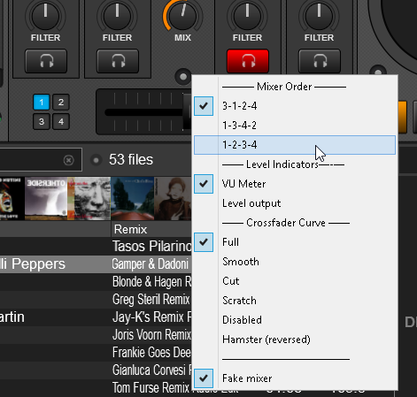
Mixer Order
By default Reloop RMX90 is pre-configured to control VirtualDJ decks with channel order 3-1-2-4. This means that the middle CH2(TWO) and CH3(THREE) are assigned* to control main decks 1 and 2 and the side Channels CH1(ONE) and CH4(FOUR) are assigned* to control VirtualDJ decks 3 and 4.
*The SOURCE selectors need to be on USB position
How to change the Mixer channel order?
- Click on the small round button right above the Crossfader (Mixer Options) to get the Mixer Options menu. (available in the 4 Decks default GUI of VirtualDJ)
- Choose one of the available mixer orders 1-2-3-4, 3-1-2-4 (default) or 1-3-4-2
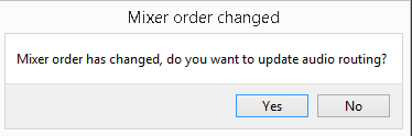
- If the sound card of the Reloop RMX90 is used in the Audio setup of VirtualDJ, confirm the change of the audio routing in the following window and VirtualDJ will automatically make the necessary changes to the audio configuration.
Mixer UTILITIES
The Reloop RMX90 is offering a Utilities menu with a few options.
How to access the Utilities menu.
- Hold both FADER START and XFADER START buttons for more than 3 seconds, until the LCD displays "USB OUT / Channel 1".
- Use the FX SELECT rotary to navigate through the available settings.
- Push the FX SELECT rotary to select a setting and adjust its value.
- Exit the Utilities by selecting the "EXIT" option. The unit will exit Utilities automatically if no selection/adjustment is made within a few seconds.
Below are the settings that are mostly useful when the unit is controlling VirtualDJ decks.
MIDI (ON/OFF)
- Enter the Utilities menu
- Navigate using the FX SELECT rotary until the LCD shows "MIDI".
- Push the FX SELECT rotary to select this setting.
- Turn the FX SELECT rotary and choose between ON and OFF.
- Push the FX SELECT rotary to apply your choice.
CUE SET (SOLO/MIX)
- Enter the Utilities menu
- Navigate using the FX SELECT rotary until the LCD shows "CUE SET".
- Push the FX SELECT rotary to select this setting.
- Turn the FX SELECT rotary and choose between SOLO and MIX.
- Push the FX SELECT rotary to apply your choice.
MIDI TYPE (Toggle/Trigger)
- Enter the Utilities menu
- Navigate using the FX SELECT rotary until the LCD shows "MIDI TYPE".
- Push the FX SELECT rotary to select this setting.
- Turn the FX SELECT rotary and choose between Toggle and Trigger.
- Push the FX SELECT rotary to apply your choice.
If set to Trigger, some MIDI functionality such as the CUE buttons will not properly work (their status will not match with the PFL indicators of VirtualDJ mixer).
MIDI CH (1 to 15)
- Enter the Utilities menu
- Navigate using the FX SELECT rotary until the LCD shows "MIDI CH".
- Push the FX SELECT rotary to select this setting.
- Turn the FX SELECT rotary and choose between a Midi Channel between 1 and 15 .
- Push the FX SELECT rotary to apply your choice.
BTH SCR
- Enter the Utilities menu
- Navigate using the FX SELECT rotary until the LCD shows "BTH SRC".
- Push the FX SELECT rotary to select this setting.
- Turn the FX SELECT rotary and choose between Master, IN1, IN2, IN3, IN4, CUE and MC/AUX
- Push the FX SELECT rotary to apply your choice.

Setup
Connections
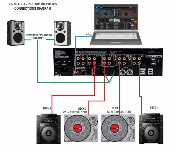
- Connect your computer to the USB port at the rear panel of the Reloop RMX90
- Optionally, connect each of your deck’s RCA cables to INPUT CH1 to CH4, depending on which software deck you wish to control.
If it’s a CD player, use any of the CD/LINE Inputs
If it’s a turntable, use the PHONE Inputs of CH1 and CH4. Secure the ground wire to a Phono Ground terminal. - Set the SOURCE selector at the top panel for DECKs 1 to 4 to USB 1/2 to 7/8
- Connect the RMX90 with AC power using the provided cable and power on the unit
Note: Usage of turntables or CD players (for DVS) is not necessary. The mixer may be used as a pure MIDI mixer. VirtualDJ is also offering the ability to control all the software decks with even with a single timecode unit. See Timecode (DVS).
Drivers
Firmware: (for both Windows and Mac OSX computers). At the time this manual is written, no update for the firmware is available, but you should also check the product's official page for any updates at http://www.reloop.com/reloop-rmx-90-dvs
Windows Drivers : Install the latest Reloop ASIO drivers from http://www.reloop.com/reloop-rmx-90-dvs
Mac OSX Drivers : No driver is required to be installed. The Mac OS will install the necessary drivers once you connect the RMX90 to a USB port.
See Advanced Setup for further settings.
.
VirtualDJ 8 Setup
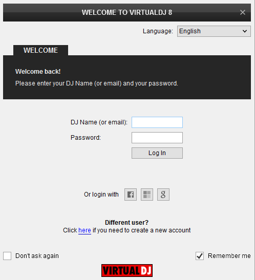
Once VirtualDJ 8 is launched, a Login Window will appear. Login with your virtualdj.com account credentials.
A Pro Infinity or a Pro Subscription License is required to use the Reloop RMX90. Without any of the above Licenses, the mixer will operate for 10 minutes each time you restart VirtualDJ.
http://www.virtualdj.com/buy/index.html
Click on the “Use Soundcard” button and VirtualDJ will automatically create and apply the pre-defined audio configuration using the built-in audio interface of the Reloop RMX90
It is suggested to select the 4 Decks Layout of VirtualDJ from the top drop-down menu.
Click to OK.
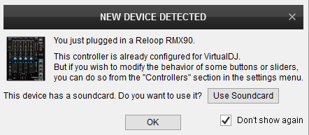
The unit is now ready to operate with VirtualDJ.
MIDI Operation
The unit should be visible in the CONTROLLERS tab of Config and the “factory default” available/selected from the Mappings drop-down list.
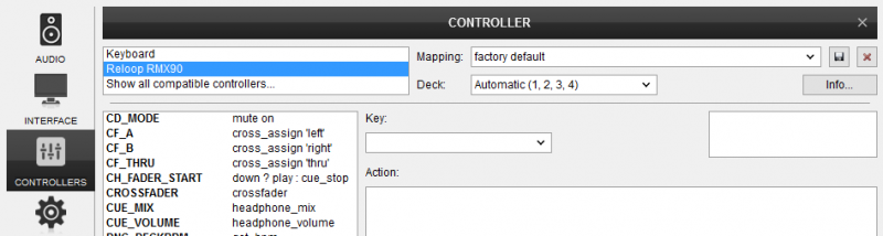
The factory default Mapping offers the functions described in this Manual, however those can be adjusted to your needs via VDJ Script actions.
Find more details at http://www.virtualdj.com/wiki/VDJ8script.html
AUDIO Setup
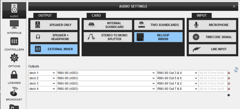
The unit has a pre-defined Audio setup and a special button in the AUDIO tab of Config to provide that. Alternative setups can be applied in the same window.
Timecode (DVS)* configuration is not pre-configured (see DVS Support for more details).
*requires Pro Infinity or Timecode License http://www.virtualdj.com/buy/index.html
For further software settings please refer to the User Guide of VirtualDJ 8.
http://www.virtualdj.com/manuals/virtualdj8/index.html
LAYOUT
Even though the Reloop RMX90 is capable of sending MIDI signals from all faders, buttons and knobs, the entire unit is not controlling the internal mixer of VirtualDJ. The audio mixing and the Effects are operated from the hardware.
The Crossfader, Equalizer, Filter, Volume faders etc. will move the relative faders of the VirtualDJ GUI, but not vice versa (Fake mixer mode)
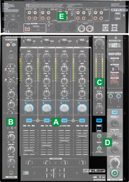
The functionality of each button, knob and connection per section (as shown in the image above) will be explained in detail in the next chapters
A. Mixer Controls
B. Headhones & Microphone Controls
C. Master section
D. Hardware Effects
E. Rear Panel
MIXER
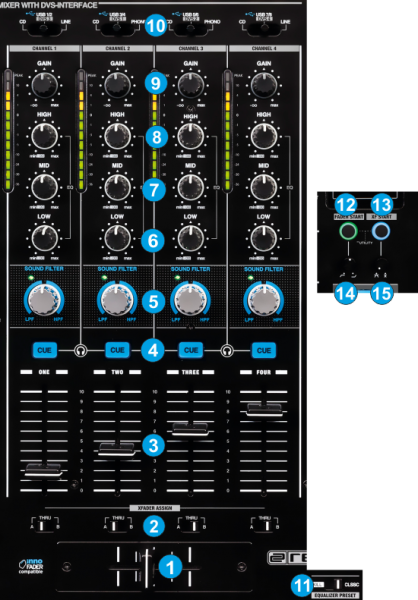
- CROSSFADER. Blends audio between the left and right assigned channels/decks.
- XFADER ASSIGN. Define on which side (A for left and B for right) of the crossfader each mixer channel will be output. If the THRU position is selected, the corresponding channel will be heard regardless the crossfader’s position.
- VOLUME. Use these faders to adjust the Output Volume of each mixer channel.
- CUE. Use these buttons to send one or more channel's pre-fader signal to the Headphones Channel for monitoring. When engaged, the button will be lit.
- FILTER.. Use these knobs to apply a High/Low-Pass Filter. When at middle (12'o clock position), no Filter is applied and the LED will be off.
- LOW. Use these knobs to adjust the low (bass) frequencies of each mixer channel.
- MID. Use these knobs to adjust the middle (mid) frequencies of each mixer channel.
- HIGH. Use these knobs to adjust the high (treble) frequencies of each mixer channel.
- GAIN. Adjusts the input audio level (gain) up to +9db of each mixer channel. No boost or cut is at 12 o’clock position.
- INPUT SELECT. Set this selector to the appropriate position to define which Channel Input will be routed to the 4 Mixer Channel Outputs
Set to USB (middle) position to route a VirtualDJ deck output to a mixer channel.
On PHONO/CD/LINE position the audio signal from the Inputs (1, 2, 3 and 4 at the rear panel) will be routed directly to the Output of this Mixer Channel. In this case the sound from the computer’s decks will be muted. Use this position to route external analogue media sources.
By default VirtualDJ decks 1, 2, 3 and 4 will be routed to mixer channels 2, 3, 1 and 4 (middle channels will control the main left and right decks). Order can be changed to your needs. See Mixer Order. - EQUALIZER PRESET. Set this switcher depending on the desired Equalizer mode. Choose between the Classic and The Kill modes.
- FADER START. When Fader Start is enabled the decks will start playing once its Volume fader moves away from the minimum position and will stop to the last Cue position when the Volume Fader reaches minimum position again.
- XF START. Not used at the moment
- FADER CURVE. Adjust the slope (curve) for the Channel Volume Faders
- XFADER CURVE. Adjust the slope (curve) for the Crossfader.
Note :
The Mixer section of the RMX90 is assigned with VirtualDJ mixer actions (moving a mixer fader/knob at the RMX90 will also move the mixer elements of the VirtualDJ mixer on the GUI) but the "fake mixer" mode is enabled since the audio mixing is done by the RMX90 and not the internal mixer of VirtualDJ. This means that whatever adjustments are made on the internal mixer of VirtualDJ (e.g. moving a Volume fader from the VirtualDJ GUI) will not affect the audio routing or output.
HEADPHONES & MICROPHONE
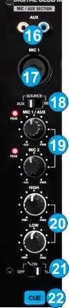
- AUX INPUT. Use this RCA Inputs to connect an analogue source such as Media Player/iPod etc.The AUX input can be also routed to a USB Interface output and sent to computer as input. See USB Channel Assign
- MIC 1 Input. Use this Input to connect a Microphone and route its signal to the MIC1 mixer input.An additional MIC2 Input is available at the front panel of the unit
- AUX/MIC. Use this switcher to select either the AUX or the MIC1 Input as Source. The selected Source will be used for the MIC1 Controls (described further in this chapter) and can be also routed as Input of the USB Audio interface to the computer.
- MIC VOL. Use these 2 knobs to adjust the output level of the MIC1/AUX and MIC2 inputs signals
- MIC EQ. Use these 2 knobs to adjust the tone (Equalizer) of the MIC1/AUX and MIC2 inputs signals
- MIC ON/OFF/TALKOVER. Use this switcher to turn on/off Microphone and Aux Inputs. When set to Talkover, the Master Output level will be reduced automatically, when signal is received from the inputs.
- CUE. Use this button to send the audio signal from the Microphone/AUX Inputs to the Headphones channel for pre-listening.
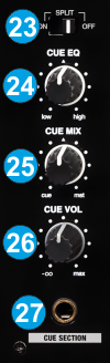
- SPLIT. When set to OFF, both sides of Headphones will output the same CUE or MASTER Outputs (depending on the CUE MIX knob. When set to ON, one side of Headphones will output the Master and the other the CUE enabled decks.
- CUE EQ Use this knob to adjust the tone (Equalizer adjust) of the Headphones Channel
- CUE MIX Use this knob to mix between CUE and Master MIX in the Headphone channel. When all the way to the left, only channels routed to Headphones (via the CUE buttons) will be heard. When all the way to the right, only the Program mix will be heard.
- CUE VOL. Use this knob to adjust the output volume of the Headphones Channel
- PHONES INPUT Connect a pair of ¼” Headphones t this socket for monitoring. An additional 1/8" Headphones socket is available at the front panel of the mixer
MASTER
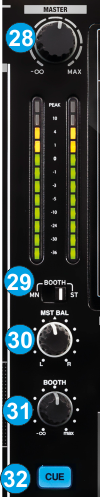
- MASTER VOL. Use this knob to adjust the Output level of the Master Output.
- BOOTH MN/ST. When set to MONO, both left and right signals will be output to both left and right Booth Outputs.
- MST BAL. Use this knob to balance between the left and right signals of the Stereo signal on the Master Output channel
- BOOTH VOLUME. Use this knob to control the Output level of the Booth Output (connection at the rear panel)
- CUE MASTER. Press this button to send the signal of the Master Output to the Headphones Channel.
EFFECTS
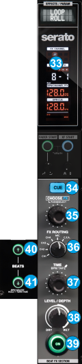
- LCD. Displays the selected BEAT FX , the Beats/Time Length or other Parameter depending on the selected Effect, along with the BPM (Tempo) value of the selected Source.
- CUE FX Use this button to send the processed audio signal from the BEAT FX unit to the Headphones Channel (to preview how the FX applies to the selected Source prior enabling it).
- FX SELECT Use this rotary to scroll though the available BEAT FXs. Push the rotary to select it.
- FX ROUTING Use this rotary to select the Source on which the BEAT FX will apply. Note that the CH numbering is always the mixer channel order and not the VirtualDJ assigned decks.
- TIME Use this rotary to adjust the Parameter (usually the length) of the selected BEAT FX. The time value (or other value) will be displayed on the LCD.
Push this rotary "on tempo" a few times to manually adjust the BPM of the FX unit if the Auto calculation is incorrect.
Push and hold for more than 2 seconds to return to the Auto mode and let the FX unit or VirtualDj to re-calculate the BPM automatically.
Note that the BPM value of each VirtualDJ deck is sent (and constantly updated) to the FX unit and the value of the selected FX Source will be displayed on the LCD - LEVEL/DEPTH. Use this knob to adjust the level/depth (Dry/Wet) Parameter of the selected BEAT FX. When at minimum 0% position, the audio signal of the selected Source will not be altered by the BEAT FX unit even if the FX is enabled.
- FX ON. Use this button to enable/disable the selected BEAT FX to the selected Source.
- BEATS UP. Use this button to half the beats/time Parameter of the selected BEAT FX.
- BEATS DOWN Use this button to double the beats/time Parameter of the selected BEAT FX. While this button is pressed, use the TIME rotary to adjust the BPM of the FX unit by 1 bpm per click
Notes
- The entire BEAT FX unit of the Reloop RMX90 is not controlling any of the VirtualDJ Effects. For those you will need to either use the controls on the GUI of VirtualDJ or an additional controller.
- For further details about the hardware BEAT FX unit, please consult the manual of the RMX90 http://www.reloop.com/reloop-rmx-90-dvs
REAR PANEL
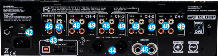
- POWER.ON/OFF. Connect a universal AC cord to the AC socket and power on the unit after all the necessary connections are done.
- USB Use a USB cable to connect the RMX90 with a USB port of your computer and allow the unit to send and receive audio and Midi signals
The RMX90 is also offering a USB hub to connect other USB devices, instead of using USB ports of your computer. - MASTER OUT (BALANCED) Connect your amplifier using a pair of balanced XLR jacks. The level of this output is controlled by the MASTER VOL knob at the top panel
- BOOTH OUT Use a pair of balanced ¼“ TRS jacks to connect the unit with your secondary output (e.g. for monitor). The level of this output is controlled by the BOOTH knob at the top panel. The RMX90 provides the ability to send a separate channel input to this Output. Selection is done via the UTILITY menu. See Utilities .
- MASTER OUT (UNBALANCED). Connect your amplifier using a pair of RCA cables. The level of this output is controlled by the MASTER LEVEL knob at the top panel
- REC OUT. Additional unbalanced Output. Use standard RCA cables and send the Master Output to an external recording device.
- CH INPUTS. 2 x Phono/CD and 2 x LINE/CD inputs are provided by RCA jacks (one for each Deck/mixer channel). PHONO Inputs on CH2 and CH3 can be used to connect turntables. CD Inputs (in all 4 mixer channels) can be used to connect CD Players. LINE Inputs in CH1 and CH4 can be used to connect other analogue Auxiliary Sources.
- CONTROL. 3.5mm mini phone jack type connections. If you connect a supported Player with the supplied Control cables, you will be able to start/stop playback with the Volume faders of the RMX90. Please consult the manual of the RMX90 for supported Players..
INPUTS & RECORDING
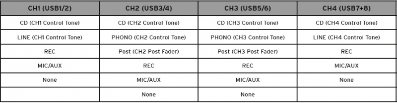
USB Channel assign
The Reloop RMX90 offers a built-in audio interface with 4 stereo Outputs and 4 stereo Inputs. The Outputs are determined by the SOURCE SELECT switchers at the top panel of the unit.
The USB Input Channels (sent to computer) can be set to different modes via the Utilities. Depending on the selected Source for each USB Channel, the inputs of the RMX90 can be used for DVS (Timecode), AUX Inputs to a VirtualDJ Deck, Recording input etc.
- Hold both FADER START and XFADER START buttons for more than 3 seconds, until the LCD displays "USB OUT / Channel 1".
- Push the FX SELECT rotary to select this setting and adjust its value.
- Use the FX SELECT rotary to navigate through the available USB Channels 1 to 4.
- Push the FX SELECT rotary to select the USB Channel that you wish to modify its source.
- Turn the FX SELECT rotary and choose between the available Sources (see table below)
- Push the FX SELECT rotary to apply your choice.
Timecode (DVS)
VirtualDJ is offering DVS (Digital Vinyl System) support for the Reloop RMX90. A Timecode Plus or Pro Infinity license is required. http://www.virtualdj.com/buy/index.html Up to 4 Timecode Inputs are available to control any software decks via Timecode CDs or Vinyls.
Mixer Channels CH2 and CH3 (middle ones) can accept PHONO (Timecode Vinyls). CD/LINE (Timecode CDs) can be accepted in all 4 available Channels.
Connect your Timecode devices at the rear panel of the Reloop RMX90 to the Inputs CH 1 to 4 and make sure the SOURCE switchers at the top panel are set to USB position.
Use the Utilities of the RMX90 to set the respective USB Channels to CD/PHONO depending on the connected DVS device.
Example 1:
In this example, 2 xTimecode Vinyls (turntables) have been connected to CH2 and CH3 and 2 x Timecode CDs have been connected to CH1 and CH4.
From the Utilities of the RMX90, we have set USB Channel1 to CD, USB Channel 2 and 3 to PHONO, and USB Channel 4 to CD. (See how, at the top of this chapter)
Open the AUDIO tab of VirtualDJ Settings and click on the TIMECODE button. By default VirtualDJ will auto-create 2 Timecode Inputs. Add 2 more Timecode Input lines and select the appropriate Input Channels as per the image below
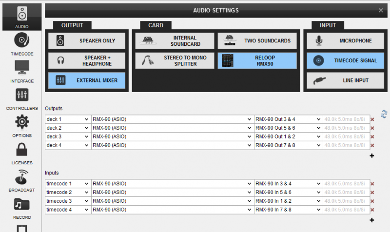
Click to APPLY.
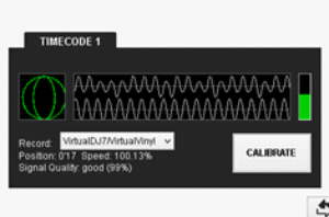
Press PLAY on your timecode CD and/or Vinyl device and VirtualDJ will automatically detect your Timecode type and make the appropriate adjustments for best performance.
Open the TIMECODE tab of the VirtualDJ Settings and choose the CALIBRATE button if for any reason the signal is not detected (possibly due to reversed phase connections).
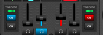
Click on the ON buttons from the TIMECODE panels of the Default Skin (in the SCRATCH center panel) to enable the Timecode control to any of the 4 software decks.
Example 2 :
In this example, 2 x Timecode Vinyl DVS devices have been connected to CH2 and CH3 at the rear panel of the Reloop RMX90 and PHONO has been selected as Source for USB Channels 2 and 3 via the RMX90 Utilities menu.
REC has been chosen as Source for the USB Channel 4 in this example. See Recording.
Recording
Any of the 4 available USB Channels of the Reloop RMX90 audio interface can be used to record your Main Mix along with Microphone/Aux Inputs.
- Use the Utilities of the RMX90 and select the REC option for any of the USB Channels
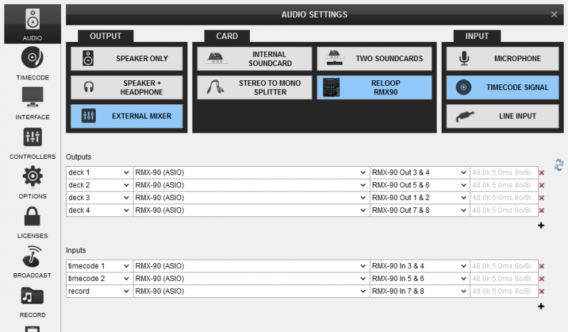
In this example, USB Channel 4 has been selected as REC source - Open the AUDIO tab of VirtualDJ Settings and manually add a “record” line to your current audio configuration. Select the Reloop RMX90 sound card and the same Input Channels from the Setting Utility (in this case IN 7&8), as per the following image.
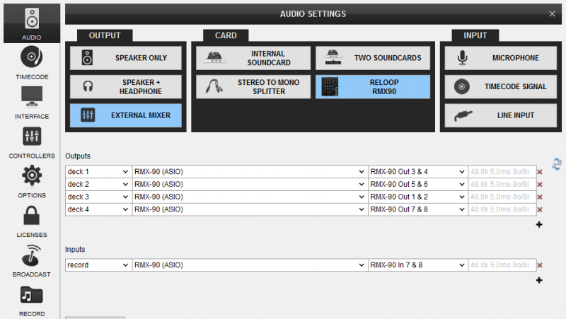
Reloop RMX90 - Audio Setup with Record line - Click to APPLY
- Open the MASTER center panel of the VirtualDJ GUI and click to the REC button (or BCAST for broadcasting) to record your mix.